By Steve Siverns | Chemical Engineer | Pureflow, Inc.
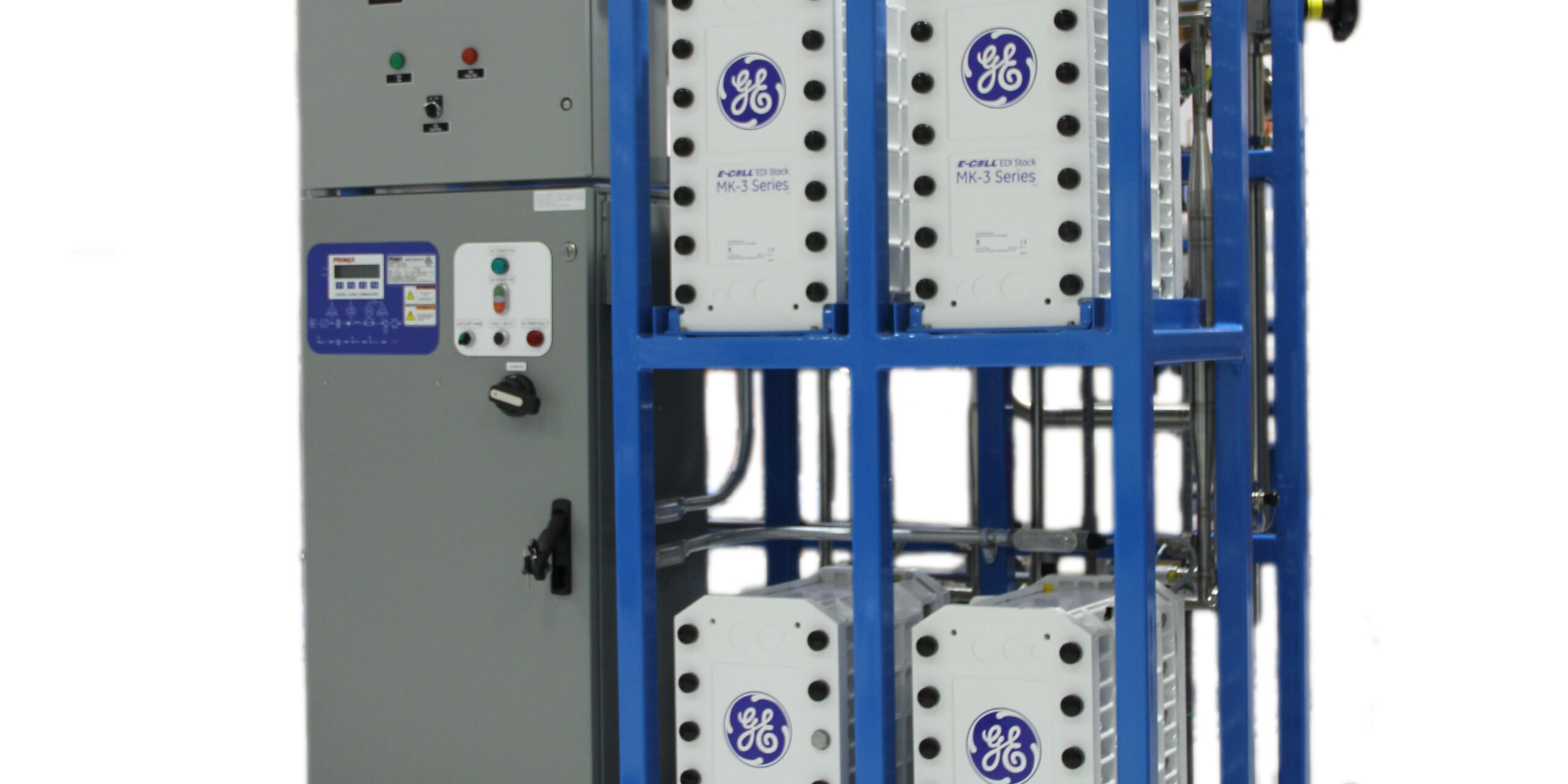
Electrodeionization (EDI, or sometimes CDI or CEDI) is a way to demineralize water using electricity as the driving force. It is used across a wide variety of industries and applications ranging from general industrial DI water through life sciences, pharmaceutical, and semiconductor grade water. Like any technology, it needs to be designed and applied properly, and it needs to be monitored regularly to ensure continued reliable operation.
EDI Technology
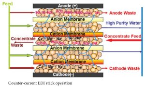
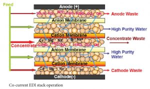
EDI has the following three processes which occur simultaneously: 1) ion exchange where the resin exchanges the ions in the water for H+ and OH- ions (just like any mixed bed ion exchange vessel), 2) ion migration from feed to concentrate chambers due to the current flowing through the stack, and 3) water splitting that occurs at the locations where cation resin and anion resin are in close contact. When water molecules are split, the water (H2O) becomes H+ and OH- ions, and these acid and caustic ions regenerate the ion exchange resin in the EDI stack. All three processes together provide continuous deionization of the feed water flow.
Water Quality
As an EDI stack is a very small mixed bed ion exchange unit, poor feed water can easily exhaust the resin and result in degraded product quality. Silica is the first constituent to break through as quality degrades. Unfortunately, silica is not easy to measure unless you have a relatively expensive silica analyzer nearby. A decrease in the resistivity of the product water is usually the first indication of water quality degradation.
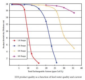
Product water quality degradation can be compensated by increasing the current (up to the maximum permitted) through the stack.
Feed water quality is critical to proper performance of the EDI. If there are too many dissolved ions in the feed water, there may not be enough electrical current to remove them, and some will pass through to the product. If there is too much silica in the feed water, the EDI may not be able to remove it all. How much is too much depends on the load of other ions present and the silica level required in the product water. Achieving 5 ppb silica in the product water is easier with feed water containing 100 ppb silica and 5 ppm other ions than with a feed water containing 300 ppb silica and 15 ppm other ions in the feed water.
The carbon dioxide level in the feed water is also very important. Carbon dioxide is not typically measured by conductivity, but it must exchange on the ion exchange resin and be removed by the electrical current like any other ion.
Fortunately, reverse osmosis (RO) technology provides excellent pretreatment to EDI. RO membranes remove a high percentage of the dissolved ions in the water and all of the particulate material. For this reason, an RO unit is always provided upstream of an EDI unit.
Product water resistivity is normally monitored continuously as this is an easy measurement. Where silica is important, it can be monitored continuously or with routine grab sample analysis.
Feed water conductivity is normally monitored continuously also. The silica and carbon dioxide levels should be checked with routine grab sample analysis. The frequency of analysis will depend on the stability of the feed water quality.
Flows
There are several flow configurations used in EDI systems. With some manufacturer’s stacks, the concentrate flow is set internally. With E-Cell stacks there is the option of running the concentrate through the stack counter-current to the feed flow or co-current to the feed flow. Co-current operation has the advantages of requiring less feed pressure than counter-current operation and of potentially higher product flow. Counter-current operation has the advantages of a simpler system design and higher feed water hardness tolerance. Higher feed water hardness tolerance is a significant advantage, so most systems are designed with counter-current concentrate flow.
Stacks have minimum and maximum specified flow rates for feed, concentrate, and (where applicable) electrode bleed lines. The maximum feed flow is determined by the ion exchange kinetics (beyond the scope of this article) and the pressure drop through the stack. Minimum feed flow is determined by ion exchange kinetics and by the ability to remove the heat generated by the electricity flowing through the stack.
The maximum concentrate and electrode bleed flows are determined by the pressure drop through these parts of the stack and by the desire to not waste any more water than is necessary. The minimum concentrate and electrode bleed flows are determined by the necessity to flush out the ions removed from the feed water. Removing the heat generated in these chambers is also necessary.
EDI recovery is the product flow divided by the feed flow (times 100%). Maximum recovery is determined by design software and is mostly a function of the feed water quality.
Product flow and waste flow(s) are normally monitored with on-line flow sensors on a continuous basis. Recovery is calculated from these numbers.
Pressures
All stacks have a maximum permitted feed pressure. Damage to the membranes and the spacers can occur at high pressures. For hot water sanitizable stacks, the maximum permitted feed pressure during sanitization is much lower than the normal operating pressure, so the hot water sanitizing system must account for this lower pressure limit.
It is important that the concentrate pressure be less than the feed/product pressure at all points in the stack. EDI membranes have imperfections, so the design must ensure that any leaks are always from the feed/product chambers to the concentrate chambers.
A counter-current feed/concentrate flow design accomplishes this automatically while a co-current flow design requires pressure regulation on the concentrate inlet line. A co-current design requires a bit less feed pressure, but the simplicity of the counter-current design makes it far more popular.
Pressure Drop
The pressure drop from feed to product, for a clean stack, depends on the regeneration level in the stack. Ion exchange resins swell when they are regenerated. In an EDI stack, the swelling reduces the space between resin beads leaving smaller passageways for water flow and thus higher pressure drop. Thus a stack run at higher current will have a higher pressure drop than a stack run at lower current, all other thing being equal.
But pressure drop can also be increased due to fouling and scaling in the stack. Too much hardness in the feed or a very high current can create scale that plugs up the passageways where the water flows. Also, although the electric field in the stack makes it difficult for bacteria to survive, it is possible under some circumstances to have biofilm develop and plug passageways.
Feed pressure and product pressure are normally monitored continuously by on-line sensors. Waste line pressure(s) (and in co-current systems the concentrate inlet pressure) are often provided with a pressure gauge. These readings should be recorded weekly at a minimum.
Power
The electrical current flowing through the stack does the work of moving ions and splitting water. Current, measured in Amps, is set at the rectifier (which changes ac to dc).
If the current is not set high enough for the feed water quality present and the product water quality desired, the ion exchange resin in the stack will be exhausted quickly and the product water quality will decline. If the current is set too high, more of the current will be used splitting water and more of the resin in the stack will be in a regenerated state than is necessary. This wastes some power. The higher current also pushes ions to and through the ion exchange membrane faster, and this can lead to accelerated hardness scaling.
The rectifier voltage is a result of the current level selected and the resistance of the EDI stack(s).
Ideally the current and voltage of each stack should be measured at least weekly. On many system designs only the total current being fed to all stacks is available (single rectifier).
Operation Trends
As with any continuously operating process, it is invaluable to have historical and trended operating data for comparison purposes. Trends show changes over time and can anticipate impending failures. Historical data allows for comparison to see if operating parameters have been adjusted or if performance has changed.
Steve Siverns is a Chemical Engineer at Pureflow, Inc. and has been a member of the Pureflow team since 2011. Steve has over 30 years of experience in design and troubleshooting of high purity water systems. He has his Masters of Engineering in Process Control from McMaster University in Hamilton, Canada and is PE registered in Ontario, Canada.
Article is re-printed with permission of Steve Siverns. Unauthorized reproduction of this article and/or use in any form is strictly prohibited without the expressed written consent of Pureflow, Inc.


