

By Richard K. Nielsen | Catalent Pharma Solutions Inc
Introduction
The US Geological Service states that the surface waters in more than half of the United States are hard to very hard. They define ranges for water hardness as follows:
0 to 60 mg/l as CaCO3 – Soft
61 to 120 mg/l as CaCO3 – Moderately Hard
121 to 180 mg/l as CaCO3 – Hard
> 180 mg/l as CaCO3 – Very Hard
In the high purity water industry there are two common measures. In metric units hardness is expressed in mg/l as CaCO3. This is equivalent as parts per million (PPM as CaCO3). In English units hardness is expressed in gr/gal as CaCO3. To convert gr/gal to PPM multiply the number of grains/gal by 17.1. In a similar manner to convert from PPM to gr/gal divide by 17.1.
There are numerous chemical test kits as well as electronic instrumentation to measure water hardness of the incoming water to your process.
Chemical test kits will have an indicator that changes color at different hardness levels. Usually, the operator can titrate drop wise a solution where the number of drops equals the hardness.
What is Water Hardness & Why is it Important?
Water hardness is a way of expressing the concentration of calcium, magnesium, iron, and several lesser important minerals that are commonly found in all surface waters. Ultimately the source of these minerals in surface waters is primarily limestone which is quite prevalent in the Earth’s crust. Subterranean water comes in contact with the limestone, and the minerals slightly dissolve in the water. These sub-surface waters will ultimately become surface waters. The minerals remain in the water until they are removed by some type of purification process. The primary mineral component of the limestone is calcium carbonate (CaCO3). The other minerals that are also present in the carbonate form co-dissolve in water that is in contact with the limestone as well.
Calcium, Magnesium and Iron Carbonate salts are only slightly soluble in water. This is the key to understanding why hardness is such an important parameter of your incoming water chemistry. Essentially, as the water evaporates, the solubility limit of the carbonate salts is exceeded, and the carbonate salt precipitates.
If not treated, it forms a thick off-white layer on pipes, tanks, heat exchanger plates, etc. This plaque reduces flow, causes increased pressure drops, and significantly reduces heat transfer in heating applications. Calcium deposits on heat transfer equipment also likely contain CaSO4 and MgSO4.
Hardness precipitation also causes soaps and detergents to clump up and leave films that are very difficult to remove. Excessive hardness in boiler tubes, for example, can completely ruin the boiler. The calcium deposits can become so hard that even acid cleaning cannot remove the precipitation. At that point the boiler tubes have to be replaced. A similar situation occurs in water purification; hardness precipitation can foul ion exchange equipment, RO membranes, and continuous deionization equipment.
How can the Hardness Minerals be removed from Incoming Water?
The best way to remove water hardness minerals from incoming water is by an ion exchange process known as softening. The closer the incoming water is to zero ppm, the less likely the water is to foul heat transfer equipment and water purification equipment such as reverse osmosis machines and continuous deionization machines. A well designed water softening system can easily reduce effluent hardness to < 1 PPM as CaCO3.
What is Water Softening?
Water softening is the ion exchange process where calcium, magnesium, and other minor minerals are exchanged with sodium. The principal component is an ion exchange resin that makes the exchange process possible. In the case of water softening, the resin is cation exchange resin in the sodium form.
There are other ion exchange processes where cations can be exchanged for hydrogen ions and anions can be exchanged for hydroxyl ions resulting in the formation of water. This article will be limited to softening (exchange with sodium).
Cation exchange resin (sodium form) consists of thousands of small spherical beads that have a very dark brown color. It is generally supplied in 1 cubic foot bags that weigh about 50 pounds. The resin is added to a processing vessel that has a layer of resin beads placed on top of a gravel base layer. The vessel has internal piping and fine screens to prevent the resin beads washing away.
Incoming water flows down through the resin bed and leaves through the bottom outlet of the vessel. This is called the service cycle. As the incoming water passes through the bed, incoming water (rich in calcium and magnesium) contacts the resin bead surfaces and is replaced by sodium.
This is a chemical reaction that is reversible. Like any chemical process, the resin has a finite capacity to exchange Ca++ and Mg++ for the equivalent of Na+. Eventually the resin becomes saturated with Ca++ and Mg++ and will no longer be removed. At that point the resin is exhausted and requires regeneration.
The saturation point is also called the point of hardness breakthrough. That means that unremoved Ca++ and Mg++ pass through the bed and raise the hardness level of the effluent water leaving the softener. Most softener systems have instrumentation that continuously measure the hardness and have an alarm to let the operator know when hardness breakthrough is starting to occur. Typically, a conservative hardness breakthrough cutoff point is 5 PPM as CaCO3 (0.3 gr/gal as CaCO3).
What is the Regeneration Process?
Once an unacceptable level of hardness breakthrough is detected (instrumentation or via a hardness test kit for manually initiated regenerations) many systems will automatically initiate a regeneration cycle. There are several key steps to a successful regeneration.
The first critical step is called the backwash. During the service cycle, incoming water flows down through the resin bed. This process causes the resin bed to be compacted. During a backwash, the water flow is reversed and flows into the bottom of the bed through the bed and out the top. Mechanically this lifts the bed softener. It also helps wash out fine insoluble particulate contaminants that have accumulated during the service cycle. Typically the next step in the regeneration cycle is the brine draw which is the reverse of the softening process. Usually a 6 to 10% w/w solution of sodium chloride passes through the resin bed allowing Na+ ions to replace Ca++ and Mg++ ions bound to the resin. The Ca++ and the Mg++ are washed out and sent to drain.
Most resin manufacturers recommend that to convert near 100% of the resin back to the sodium form, a large excess of NaCl should pass through the resin bed in the forward direction (in the top, through the bed and out through the bottom of the vessel). Typically 15 lbs of NaCl is used per cubic foot of resin.
Let’s give a practical example:
Suppose we are given the following information:
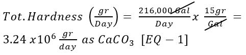
- Our Facility uses on average 216,000 gallons of soft water per day. This corresponds to 150 gpm. [Given 1].
- The average water hardness is 15 grains/gallon as CaCO3 [Given 2].
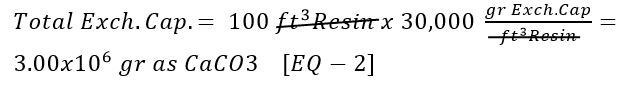
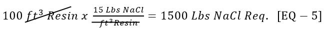
- We have a duplex pair of softeners where each has 100 ft3 of Cation Exchange Resin. [Given 3].
- The cation exchange resin has a capacity of 30,000 gr/ft3 Resin as CaCO3 [Given 4].
- We have an ample supply of saturated sodium chloride (26% w/w NaCl) available in our outdoor brine maker system. [Given 5].
- We have designed to Softener to regenerate using 15 Lbs NaCl/ft3 of Resin [Given 6].
- Our Brine system has an eductor that dilutes the 26% NaCl to 10 % w/w NaCl. The softener actually uses the diluted 10% solution during the brine draw [Given 7].
- We have looked up the density of the 26% w/w salt (1.1993 Kg NaCl/ Kg 26% Solution). In the same table we have the density of the 10% w/w NaCl (1.0726 Kg NaCl/ Kg 10% Solution) [Given 8] & [Given 9].
- We want the brine draw time to be 45 minutes. [Given 10].
We will now use an engineering calculation technique known as dimensional analysis to see what is required to regenerate our softener.
What is the total hardness of the incoming water on a daily basis?
Use [Given 1] and [Given 2]:
What is the total exchange capacity of each softener?
[Typically with a duplex system, only one softener is in service at any given point in time. The second unit is in standby and is already in a regenerated state (Sodium form). When the softener in service exhausts, the control system switches to the standby unit. The exhausted unit regenerates and then goes in to the standby mode. The softeners alternate between service and standby modes].
Use [Given 3] and [Given 4]:
What is the typical expected throughput between regenerations?
[Typically softener systems regenerate one of three ways:
- on a hardness basis (5 ppm Threshold)
- on a time basis
- on a throughput (volume) basis].
Use [EQ-1], [Eq-2] and [Given 1]:

- Hardness based regenerations should be based on actual performance and testing. We typically see the leaving hardness just hit the cutoff threshold of 5 ppm near the end of the service cycle. We have reduced the volume cutoff to reduce the frequency of seeing the hardness alarms.
How much NaCl is required for each Regeneration?
Use [Given 3] and [Given 6]:
How may lbs of salt are in one gallon of 26% NaCl solution?
Use [Given 5], [Given 8], some common conversion factors and the definition of % w/w:

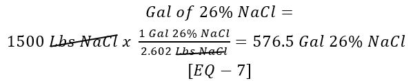
How many gallons of 26% NaCl solution are required to yield 1500 lbs of NaCl?
Use [EQ – 5] and [EQ – 6]:
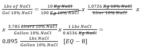
How many lbs of salt are in one gallon of 10% NaCl solution?
Use [Given 9], some common conversion factors and the definition of % w/w:
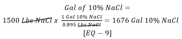
How many gallons of 10% NaCl solution are required to yield 1500 lbs of NaCl?
Use [EQ – 5] and [EQ – 8]:
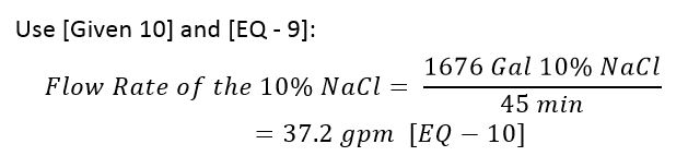
What is the flow rate of the 10% NaCl to the softener?
Use [Given 10] and [EQ – 9]:
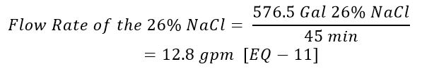
What is the flow rate of the 26% NaCl to the eductor?
Use [Given 10] and [EQ – 7]:
What conclusions can we draw from the above calculations?
- The most important calculations are presented in [EQ – 3] and [EQ – 4]. Based on the given information each softener will require regeneration approximately one per day (22 hours by calculation). This corresponds to 200,000 gallons between regeneration by calculation.
- It has been the author’s experience that over time this throughput will decrease. This has been most likely due to resin loss during backwash. It only takes a few backwash cycles with an excessive flow rate to wash out resin. I will discuss this in Part II of this article in much more detail.
- The next set of conclusions is about the brine system. Failure to properly design the brine system will result in very poor softener performance.
Design of the Water Softener Vessel & System:
Benefits of a Duplex System:
Typically softener systems are set up as a duplex system. At any given point in time, one vessel is in service, and the second vessel is either regenerating or is in a standby mode. Standby means that the off-line vessel has been regenerated and the resin is in the sodium form. The standby vessel is pressurized, and the service valve is closed.
When the current on-line vessel exhausts (time / hardness or volume basis), the control system brings the standby unit into service and then automatically initiates a regeneration cycle on the exhausted unit. Upon completion of the regeneration, that vessel goes into the standby mode as the process repeats itself.
After the regeneration has been completed, the control system automatically refills the brine day tank with 26% salt pumped over from the outside brine maker.
The key benefit of the duplex system is that the facility always has soft water available; there is no downtime waiting for the single unit to regenerate.
Materials of Construction Considerations:
Due to the high salt concentrations, materials of construction are a very important design consideration. First and foremost are the two softener vessels themselves. Generally speaking, steel vessels are used for large softeners. For smaller systems, where the vessels are less than 36 inches in diameter, FRP vessels are often specified.
Steel vessels must be lined; otherwise the salt would destroy the steel and eat through the vessel eventually. Notwithstanding, the carbon steel would put iron back into the water that we are trying to purify.
There are several lining options available. The least expensive and also the least preferred option is a painted-on epoxy liner. Over time, the epoxy scratches and peels away from the steel substrate, and we are right back to having bare carbon steel exposed to the harsh salt conditions.
A second option is a sprayed-on epoxy or phenolic liner (almost like a sprayed-on bed liner for a truck). This is superior to the painted-on option but still has the potential to delaminate from the steel substrate. Once compromised, we once again have bare carbon steel exposed.
Other options are a sprayed-on PVC liner. The best available liner is a food grade rubber liner. Softeners used at Catalent have a 3/16” thick FDA approved rubber liner. Liners are typically spark tested using more than 10,000 VDC and a very low amperage to assure complete coverage. If there are any defects in the liner, the wisk (@ > 10,000 VDC relative to the grounded steel substrate) will arc clearly indicating that the liner is compromised. The tester moves the wisk over the lined surface of the vessel looking for defects in the lined surfaces. All internal components are either covered with rubber or are 316 L stainless steel.
Face piping and interconnecting piping is another important consideration. Any piping and valves that is in direct contact with either 10% or 26% salt should be either Schedule 80 PVC or polypropylene. Piping exposed to outdoor conditions should be coated to protect the piping from UV exposure from direct sunlight. PVC piping will become brittle over time when it is exposed to direct sunlight.
Face piping can range from stainless steel to PVC or polypro piping and components. Valves should also be a suitable plastic or stainless steel. Many times valves will have 316 SS internals with enamel coated steel substrates.
Vessel Sizing Considerations:
Most municipalities will require that the softener vessels meet ASME requirements for Pressure Vessels. At a minimum, the vessel should be rated
for > 100 psig and hydrostatically tested during fabrication to 150% of the MAWP (Maximum Allowable Working Pressure). ASME rated vessels are provided with a National Board Stamp on the vessel itself and a Form U1 to document the design specifications along with the MAWP and the testing that was performed.
The optimum dimensions for a vessel that minimizes the surface area of the side wall is when the inside diameter of the vessel equals the straight side height of the vessel. This fact, in conjunction with the ASME requirements, fixes the sizing of the vessel.
However in most cases the straight side of the vessel must be extended to provide additional freeboard. Freeboard is the volume of water above the top of resin bed. This is critical during the backwash step of the regeneration.
During backwash the bed lifts and expands. Good design practice is to allow approximately 35% to 50% freeboard to allow room for the bed expansion. The figure shown below is dimensions for a 100 ft3 softener with 25 ft3 of gravel underlayment.
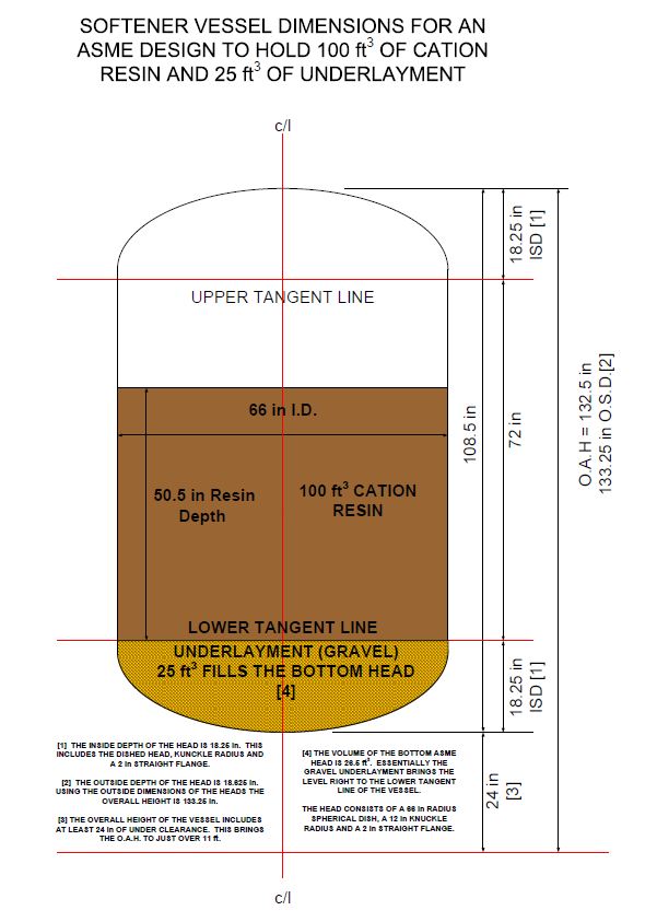
Ideally the author would like to have had several more inches of freeboard; however, we had to deal with a height restriction. The above design provides 36% freeboard. The overall inside vessel volume is 195.5 ft3. The resin and underlayment occupy 125 ft3. That leaves 70.5 ft3 of volume above the resin bed. The % freeboard is the ratio of the volume above the resin bed to the overall vessel volume expressed as a percentage.
Ideally, the straight side height should be 80 in, which would have increased the freeboard to 40.8%. However, the OAH would then be 11’ 8” which is too tall.
Other Important Design Considerations – Flow Rates
Specifying the Service Cycle Flow Rate:
Generally, the designed service flow rate is based on one of two factors. The first is called superficial velocity. This is the ratio of the flow rate in gpm to the cross sectional area of the vessel. Typically a range of 4 to 10 gpm/ft² is recommended with a design of 8 gpm/ft². For the vessel above, the sectional area is 23.8 ft². Using 8 gpm/ft² gives a recommended design service flow rate of ≤ 190 gpm.
The second method for determining the service flow rate is called space velocity. This is based on the volume of resin. Space velocities are typically 0.2 to 5 gpm/ft3 resin. The usual design parameter is 2 gpm/ft3. Thus, based on this space velocity, the flow rate should be ≤ 200 gpm.
200 gpm flow rates are in the 3 to 4 inch piping / valve size range.
Specifying the Regeneration Cycle Flow Rates:
Step 1 – Backwash:
Approximate Space Velocity: 1 gpm/ft3 resin
Approximate Duration: 15 minutes
Example Design (100 ft3 cation resin): 95 gpm for 15 minutes
Step 2 Brine Draw:
Approximate Brine Concentration: 10% w/w NaCl
Approximate Space Velocity: 0.3 to 0.4 gpm/ft3 resin
Approximate Duration: 45 minutes
Example Design (100 ft3 Cation Resin): 10% NaCl @37 gpm for 45 minutes
Step 3 Slow Rinse:
Approximate Space Velocity: 0.2 to 0.3 gpm/ft3 resin
Approximate Duration: 45 minutes
Example Design (100 ft3 Cation Resin): 25 gpm for 45 minutes
Step 4 Fast Rinse:
Approximate Space Velocity: 1 to 1.5 gpm/ft3 resin
Approximate Duration: 30 minutes
Example Design (100 ft3 Cation Resin): 120 gpm for 30 minutes
Step 5 Place Unit in Standby Mode:
The regenerated unit remains in standby until the unit in service exhausts. The service valve remains closed. However, the unit remains pressurized with water.
Step 6 Brine Tank Refill:
The Brine Day Tank refills with 26% NaCl. The level controller shuts off the refill valve when the tank is full. A second regeneration cycle of either unit is disabled while the brine day tank refills. Since 576 Gallons of 26% NaCl were used for the regeneration, refills will take approximately 38 minutes @ 15 gpm.
The Author: Richard K. Nielsen
Mr. Nielsen has 40+ years of experience in both the liquid and soft gel pharmaceutical industries. Most of that experience has been focused on high purity water systems. This includes design, engineering, installation, validation and maintenance of these types of systems. He holds a BA degree in Chemistry (UMBC 1975), a BSE in Chemical Engineering (UMBC 1992), a MSE in Industrial Engineering & Statistics (Purdue 2015). In addition, he is a Certified Quality Engineer (ASQ 1986) and is a registered PE in the Chemical Engineering Discipline (Maryland 1998).
Article is re-printed with permission of Richard Nielsen. Unauthorized reproduction of this article and/or use in any form is strictly prohibited without the expressed written consent of Richard Nielsen.