

By Harv Scholz, PE | Pureflow, Inc.
Heat Exchanger Basics
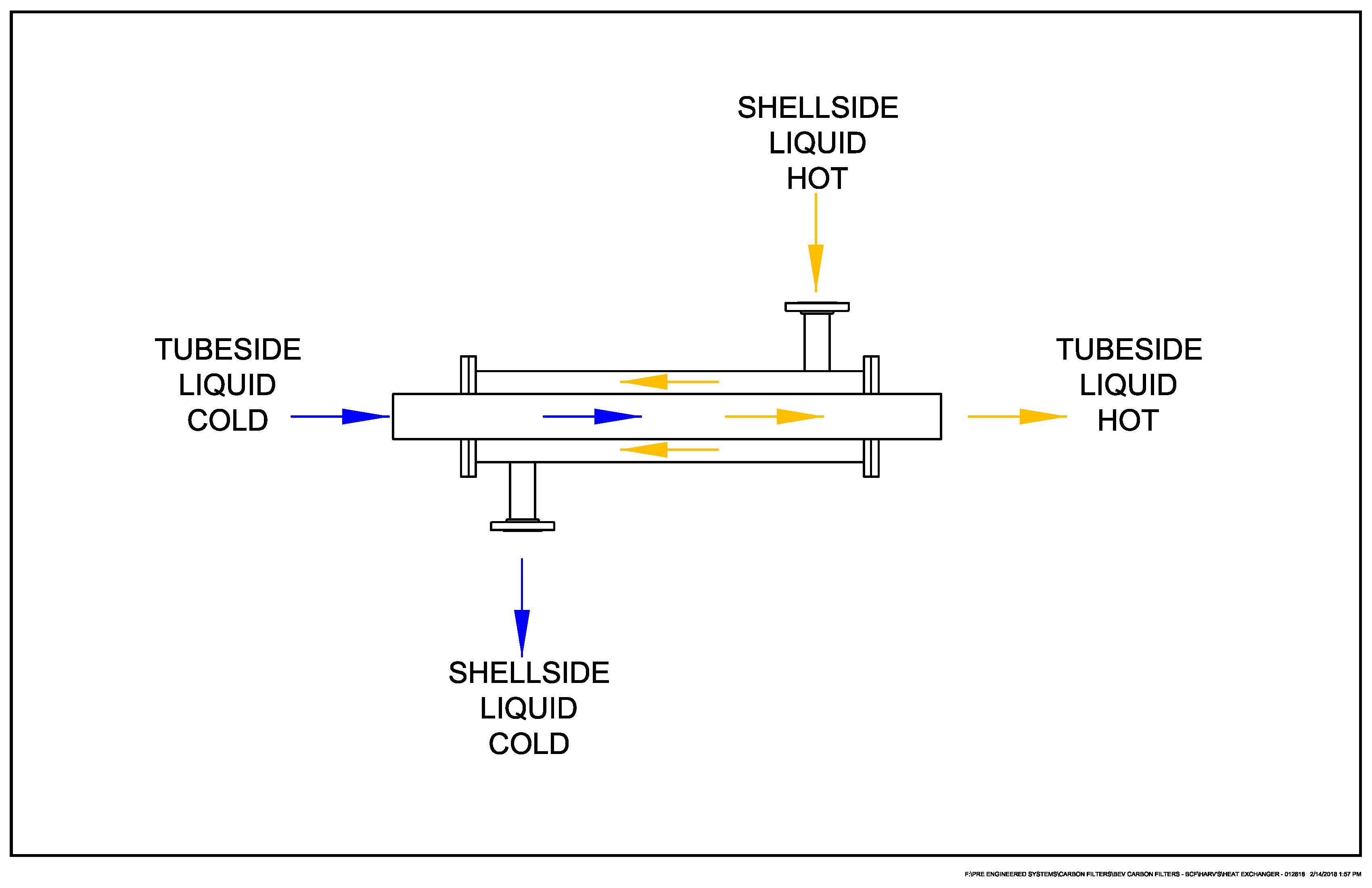
A heat exchanger is a device used to transfer heat from one process stream to another, without having the two streams mix. These units are typically made of stainless steel, at least on the pure water side, and can be stainless steel or carbon steel on the heating/cooling medium side. A simple tube-in-tube heat exchanger is illustrated below. In this case a hot liquid is going through the shell (outer chamber), and the cold liquid is passing through the inner chamber, receiving heat from the shell-side liquid and therefore coming out the tube-side at a higher temperature.
 In water purification systems heat exchangers are used in several applications:
1.To cool the purified water as it circulates through a distribution loop – The pumping power builds up heat in the water, as does passage of the water through sterilizing or TOC removal UVs. A heat exchanger with chilled water circulating through it will keep the process water cool, typically at 70° F, to reduce the growth of bacteria.
2.To sanitize a distribution loop with hot water – Periodically a purified water distribution loop and storage tank must be sanitized to kill bacteria. This can be done with ozone or chemicals. An alternative is to heat sanitize the system with hot water at 176°F (80°C) minimum. This eliminates chemical handling and the concerns about rinsing chemicals out of the system. The water can be effectively heated and cooled with a shell and tube heat exchanger using steam as the heat source, and chilled water as the cooling source.
3. To sanitize activated carbon tanks with hot water– Some industries use activated carbon tanks to remove chlorine compounds, organics, and undesirable taste and odor from city water prior to production. An effective method of sanitizing carbon tanks is by circulating hot water at 180°F+ through the carbon bed. A heat exchanger can be used to heat water for carbon sanitization using plant steam as a heat source.
4. To preheat water for a chemical process – Most chemical processes are more effective when the chemical mixture is heated. This principle is used in almost all CIP (clean-in-place) processes.
Heat Exchanger Sizing
To size a heat exchanger for one of these applications, the vendor must know flow rates and temperatures of each fluid going through the exchanger. He also needs to know size limitations, pressure drop limits, and contaminants that may foul the heat transfer surfaces. There are many other factors that influence the heat transfer calculation, such as tube size, viscosities of the liquids, thermal conductivity of the liquids, and potential fouling of the heat transfer surfaces by contaminants in the steam or water. The complicated sizing process is typically done with a computer programmed for this specific function.
Types of Heat Exchangers
The heat exchangers used for water purification processes are usually one of the types listed below:
• Shell and Tube – Consisting of an outer shell or pipe which encloses a bundle of smaller tubes. The process liquid typically flows through the insides of the tubes, while the heating or cooling medium flows across the outside surfaces of the tubes.
U-tube heat exchangers as shown in the image above are commonly used by Pureflow because they are an economical construction that works well with clean fluids on the inside and outside of the tubes. The free ends of the U’s allow the tubes to expand or contract as the temperature changes, eliminating stress on tubesheet joints and providing dependable, long-term reliability. Most of the Pureflow shell and tube heat exchangers are ordered with tubes rolled (tube ends expanded tight against the tubesheet hole by using a special roller tool) and then welded to the tubesheets. In sanitary construction the tube end welds are then ground and polished smooth. Inside polished finish is typically 32Ra, but can be a finer finish, such as 25Ra, and possibly electro-polished, if necessary.

The sanitary shell and tube exchangers used by Pureflow are typically double tube sheet designs, where one tube sheet seals the shell-side fluid inside the shell, and the other, separated from the first by an airgap, seals the tube-side fluid inside the bonnet. This insures that the two fluids cannot accidentally mix should a leak in a tube sheet joint occur.
If the tube-side liquid is dirty and prone to fouling the tube-side surfaces, a straight tube heat exchanger is preferred. This design has a bonnet or cap at each end, allowing full access to both ends of the exchanger. This allows for cleaning operations on each tube, such as rodding through with a brush, or spraying with high pressure water through a lance.
A straight-tube heat exchanger with 2 passes of the tube-side liquid is shown to the right. Multiple tube-side passes are used when there is a limitation on length. Multiple passes can be used on the shell side also, when that flow is lower than desired in a large shell. Flow arrows indicate the paths of tube-side and shell-side fluids. Removable bonnets on each end allow for access to the tubes for cleaning, should that be required.
Note that on the shell side of the heat exchangers above, there are baffles that force the shell-side liquid to pass across the tube bundle rather than flowing parallel to the shell. This improves heat transfer significantly.
Advantages of Shell and Tube Heat Exchangers
o Rugged construction – allows for higher working pressures
o Minimal gaskets/ O-rings, which means years without maintenance
o Can be made virtually free of cross-contamination by using double tube sheets and welded tube joints.
o Sanitary construction with polished surfaces that are easy to manufacture
• Plate and Frame Heat Exchangers – This type of heat exchanger consists of a series of embossed or corrugated stainless steel plates with gaskets between them, stacked together in such a way that one fluid goes through alternate spaces between plates, while the second fluid goes through the remaining alternate spaces. The fluids are distributed and collected at ports in each corner of the plates. Gaskets with holes in specific patterns determine which fluid will go through each space. On the ends of the stack are thick carbon steel or stainless steel plates that are pushed in by screw assemblies to compress the plate and gasket assembly so that it maintains a seal under pressure. Flow inlet and outlet connections will be on the fixed end-plate.

Flow Paths through Plate and Frame Heat Exchanger Assembly
The plates are corrugated to promote turbulent flow for good heat transfer.
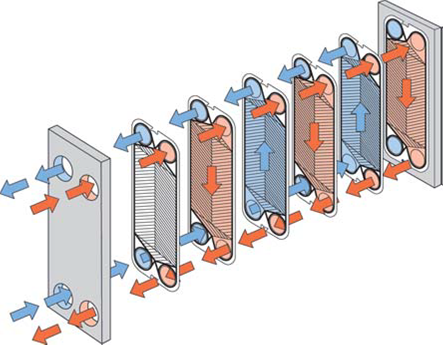
Plate and frame exchangers are an economical way to achieve large heat transfer area in a small space. However, they do have a risk of leakage from one side to the other or to the outside. Even though the manufacturers claim they work on steam applications, the harsh temperatures and pressures of steam usage will require more frequent gasket changes than in shell and tube exchangers. These gasket changes can be costly and time consuming, thereby negating the initial cost advantage of the plate and frame units for steam.
Although the actual stack of plates may not be very thick, the frame length will be significantly longer to allow for expanding the stack for inspection, cleaning, and gasket changes. Insulating these exchangers can be difficult. In most cases the insulation jacket will be made to cover the entire expanded volume. The insulation jacket also needs to be removable, sometimes in several sections, to allow for access to the heat exchanger stack. This means the jacket is more susceptible to damage by the additional handling.
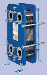 The Alfa Laval T6 plate and frame heat exchanger design shown to the right is made specifically for heating water with steam. The plates are wider and shorter to reduce steam velocity and therefore erosion and noise. The design also reduces water velocity and pressure drop.
Advantages of Plate and Frame Heat Exchangers
o High overall heat transfer capability – For the same two fluids and flows, a plate and frame heat exchanger typically has a higher heat transfer rating than a shell and tube heat exchanger.
o Compact design – The combination of a high overall heat transfer coefficient and the general compact configuration of the plate and frame heat exchanger enables it to have the same thermal capacity as a larger shell and tube heat exchanger.
o Easy maintenance and cleaning – A plate and frame heat exchanger can easily be disassembled for cleaning or gasket changes.
o Lower initial cost – The cost is typically lower than shell and tube, but gasket changes can be costly.
Heat Exchanger Applications – Water Heating Skid
The skid above is a shell and tube heat exchanger system used for heating water for process use and for hot water sanitization. To make this system, additional steam and condensate handling items have been added. These include manual isolation valves, an automated steam shutoff valve, a steam control valve, a condensate pump trap, and several smaller steam and condensate vents, traps and drains.
To download/print this TechNote, please click here for the pdf.
Harv Scholz has been a Senior Mechanical Engineer at Pureflow, Inc. for over 15 years. He is a licensed professional engineer who has a B.S. and M.S. in Aerospace Engineering.
Article is re-printed with permission of Harv Scholz. Unauthorized reproduction of this article and/or use in any form is strictly prohibited without the expressed written consent of Pureflow, Inc.